Geologic Processes on the Moon/Cratering on the Moon
|
The surface of the moon is generally divided into two types of terrain, highland ‘heavily cratered’ terrain, and volcanic maria (Fig 1).
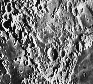
However, while the maria appear to have relatively few craters from earth-based telescopic observation, this is not the case with higher-resolution spacecraft imagery. Indeed, when the Ranger series spacecraft imaged the moon, it was seen to have craters throughout (Fig 2). While the maria are covered with small craters, they are relatively lacking in craters large enough to be seen through earth-based telescopes. This is because larger impacts occurred relatively early in the moon’s history (over the first billion years of its existence): the highland regions record these early impacts. The maria were resurfaced by lava, covering over these larger craters. Since the end of maria formation, the majority of impacts were smaller, resulting in the smooth appearance of the maria from earth-based telescopes.
Craters cover the surface of the moon and are the result of hyper-velocity impacts by meteorites. The velocity of meteorites upon impact varies, but is generally between 10 and 40 km/sec. This number is a combination of the ‘approach velocity’ and the ‘escape velocity.’ The approach velocity of objects refers to the velocity of the object with respect to the moon. This varies with the type of object (for example, long period comets generally have a higher approach velocity than short period comets) and the direction with which it approaches the moon (for example, if it approaching the moon ‘head on,’ it will have a higher approach velocity than if it is ‘catching up’ with the moon in its orbit). The escape velocity is a measure of the extra velocity an object gains as it accelerates in the gravitational field of an airless moon/planet. For the moon, this number is 2.4 km/sec.
The velocity of a bolide (the technical name for a body that strikes any planetary surface) is important for it is the major determinant of the amount of energy released upon impact. Bolides possess ‘kinetic energy’, and the value of this is proportional to the mass of the bolide multiplied by the square of the velocity. Thus, if two meteorites of the same mass strike the lunar surface, but one has twice the velocity of the other, than the faster one possessed four times (not two times) the kinetic energy of the slower one.
Upon striking the moon, the kinetic energy is transferred to a massive shock wave which both goes down into the moon’s surface and rearward into the bolide itself. The shock wave that goes rearward is so powerful that it exceeds the strength of the rock—indeed, most of the bolide vaporizes. The shock wave that goes forward into the moon vaporizes part of the surface of the moon (several times the mass of the bolide), melts layers of rock below this (up to 100 times the mass of the bolide), and shocks (fractures) the surface layers to great depth. This period in the cratering process is called the ‘contact and compression’ phase.
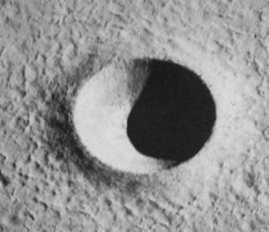
The next period in the cratering process is called the ‘excavation’ phase. This phase begins with the formation of a release (rarefaction) wave that develops at the edges of the impact, and forms a route of escape for some of the vaporized/melted/shocked rock. This escape of material produces the crater itself, and the material that escapes forms the ejecta that goes outward onto the moon surface (Fig 3). After the removal of ejects, the creater is bowl shaped, and called the ‘transient crater’ form. It is called ‘transient’ because the crater will undergo a number of later changes before assuming its final form. Lastly, the decaying shock wave continues to travel through the bedrock of the moon, creating effects further away (such as activating older faults, creating landslides, etc.).
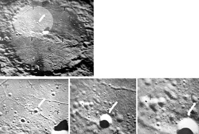
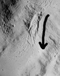
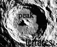
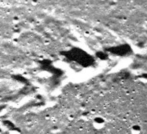
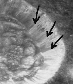
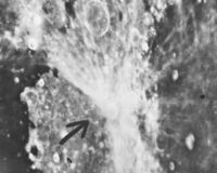
The third period in the cratering process is called the ‘modification’ phase. Here the liquid materials on the crater’s sidewall (impact melt) and semi-stable rim materials slip down to the crater’s floor (Fig 4; impact melt flowing in the direction of the arrow). Additionally, in larger craters, this is the time that the central peaks and sidewall terracing occur (Fig 5). The peaks form from rebound of compressed floor materials. The terraces form due to heavy loads (the rim materials) sitting on deeply fractured ground (the fractures are from the shock wave of the impact). Here the rim material activates the fractures, causing them to slide in a stepwise fashion. This leaves us with the final crater form.
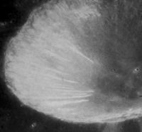
One final modification needs to be addressed. At the end of the modification phase, much solid debris sits on the rim of the craters. When shock waves from other impacts cross the rim, some of this material will fall into the crater as small landslides (Fig 6). While these slides are not visible from earth-based telescopes, they are interesting to see in space craft imagery.
From this brief description on the mechanics of crater formation, we will now look at the types of craters and the unique morphology of each. While craters are variously classified, based on their size and morphology, I am going to use the most common classification: simple craters, complex craters, and basins.
Simple Craters
Simple craters are bowl like depressions in the lunar surface (Fig 7). They occur from submillimeter size to approximately 15 km in diameter (15-20 km is the transition zone between simple and complex craters).
Simple craters form when small meteorites strike the moon at high velocities. The bolide is vaporized along with the surface struck (the target). This vaporized rock is injected into the floor of the crater, and follows the release wave to escape outside where it will be emplaced as ejecta. As the shock wave begins to dissipate, the next layer of target materials will not be vaporized, but only melted (called ‘impact melt’). This material is also injected into the crater’s floor and escapes to the outside as ejecta. As the shock wave further dissipates, it is no longer able to melt the target materials, but instead only fractures the rock. This fractured rock is again pushed in both directions.
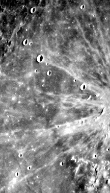
The crater itself is formed by decompression along the sides of the crater, allowing these vaporized, melted, and shocked fragments to escape. This material will lay itself down as the ejecta blanket, which has four distinct parts. Just outside of the crater rim is the zone of continuous ejecta, which is formed from the last material ejected from the impact (Fig 8; section labeled “C”). The next layer out is the discontinuous ejecta, which interfingers with the surrounding lunar surface (Fig 8; section labeled “D”). Further out yet is the bright ray system, which is formed from the first material ejected (Fig 9). The fourth part of the ejecta is found in the area of the discontinuous ejecta and just beyond it--this is the area of ‘secondary cratering’, which results from ‘chunks’ of rock which are thrown out from the crater (Fig 8; section labeled “S”). This secondary cratering typically forms a ‘herringbone’ pattern on the lunar surface, with multiple craters in a line having small ‘v’ shaped lines emanating from them (Fig 10; this can’t been seen in earth-based telescopes).
Once the ejecta has exited, the remaining crater is called the transient crater, for other processes will modify its final form. For simple craters, this final ‘modification’ involves the sliding down of impact materials (impact melt and unstable rim/wall materials) onto the floor of the crater. For craters in this size range, these materials generally fill the lower third to half of the transient crater’s depth. This will result in the crater’s final form.
Observation of such a crater will reveal a bowl shaped depression with a sharp rim, some rim deposits (blocks of material thrown out at the end of excavation), a discrete ejecta blanket grading from continuous to discontinuous, and a bright ray system. Across time, parts of this crater will degrade due to the erosive rain of micrometeorite impacts. The first structural element to disappear will be the ray system, followed by the discontinuous ejecta and the sharp rim. This process will continue until only a bowl shaped depression with a gentle slope remains.
Complex Craters
Complex craters begin at 20 km (transition zone from simple to complex is 15-20 km in diameter. They are characterized by the morphology of a bowl like depression with a central uplift of one of more massifs (small, mountain like structures) and terracing on the sidewalls (Fig 5).
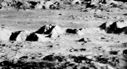
Complex craters form when medium sized meteorites impact on the lunar surface. The impact occurs as discussed in the simple crater above, though the energies involved are much greater. The real differences begin after the formation of the transient crater, during the stage of “modification.” At this point the rim is more massive than in a simple crater, being piled high with ejected crater materials. Because the subsurface rock is extensively fractured, this rim material cannot be supported. It slides down these fractures (called ‘slumping’) creating a series of ‘terraces’ on the crater’s inner walls. Central peak or peaks also form at this time (Fig 11: side view of the central peaks in Crater Copernicus). Peaks form because the impact compresses the underlying rock, and this rock rebounds after the shock energy is dissipated—much like a bedspring that is compressed and then released (the size of the central peaks is also modified by slumping of the rim material, which pushes rock towards the central uplift). At the same time that the processes of slumping and peak formation are occurring, the impact melt on the sides of the crater is sliding down to the crater’s floor. This again covers the bottom of the temporary crater and ponds in some of the terraces (Fig 4). These processes result in the ‘final’ form of the crater
The parts of the complex craters are, then, the central uplift, which can be one or several peaks that may attain heights of over a 1000 meters. Moving form the central peak(s) outward, we encounter a flattened floor of impact melt which grades into the terraced sidewalls. The rim occurs at the top of the crater and grades out into the continuous ejecta, the discontinuous ejecta, the larger secondary craters (which can be seen by earth based telescopes; for e.g., see those around Copernicus), and the bright ray system.
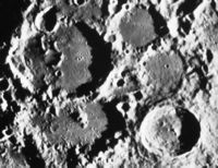
Degradation occurs in complex craters as in simple craters. First the ray system goes, followed by discontinuous ejecta and the sharp rim. The continuous ejecta erodes later along with the terracing and central peak. Across geologic time, the crater will become a simple bowl like depression (Fig 12 shows craters in various states of degradation).
Basins
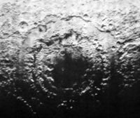
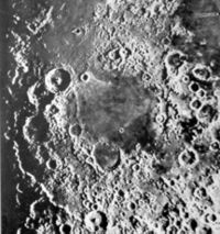
Basins begin around 200 km in diameter (note: given the length of this article, I will not further divide basins into peak-ring basins, central-peak basins, and multi-ring basins; the reader is referred to more detailed texts by clicking on each image). Basins are characterized by a series of rings, instead of a single rim (fig. 13: the Orientale Basin; fig. 14; the Nectaris Basin). Multi-ring basins are the largest cratering events on the moon, spanning up to 2500 km in size. The formation of multi-ring basins is poorly understood, and competing theories exist. The problem is that the amount of kinetic energy released is so large that it is difficult to predict how solid surfaces behave under its influence. The model we present assumes that the energy causes the solid lunar surface to behave as a substance with little inherent strength (i.e., a fluid surface), and so the rings form like a stone dropped into still water.
When a massive impact occurs on the moon, the transferred energy produces a massive shock wave. This vaporizes most of the bolide (the impacting object) and part of the moon’s surface. As in the simple crater, this material is both injected into the next layer (i.e., deeper into the lunar surface) and allowed to escape as ejecta. Much of this initial ejecta has a velocity that exceeds the ‘escape velocity’ of the moon, and so enters the interstellar medium. Some of this material later falls into earth’s atmosphere.
Once the shock wave has dissipated some of its energy, the shock wave no longer has sufficient energy to vaporize surface materials. At this stage, the shock wave only has sufficient energy to melt rock. This layer, of melted lunar surface rock, is both injected deeper into the lunar surface and allowed to escape as ejecta. After the shock wave has dissipated more of its energy, it is only able to ‘shock’ the rock. This layer is, again, both pushed deeper into the lunar surface and allowed to escape as ejecta.
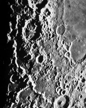
The ejecta of vaporized rock, melted rock, and shocked rock produces the crater itself. This initial ‘crater,’ called the transient crater, is in the shape of a shallow bowl. Next a central uplift occurs, as with complex craters (see ‘part one’ of this series). This central uplift is due to the rebound of the rock underneath the transient crater. This rock was compressed by the shock wave, and here—like a bedspring suddenly released—it rebounds in an upward movement of floor materials. However, this rebound cannot come into equilibrium—it can’t form a central peak, as in complex craters. This is because the crater’s floor is acting more like a fluid—it has little inherent strength. So the rebound material collapses, and forms a wave that spreads out in all directions. The wave freezes in place as its kinetic energy is dissipated by friction (fig 15: Rupes Altai, which is one of the outer rings of the Nectaris basin). Multiple rings may form in this fashion.
The morphology of a multiring basin is best illustrated by the Orientale basin (fig. 13). While it is the most recent of the large basins, only a fraction of it can be seen from earth. Fortunately, it is well photographed by spacecraft. The center of the basin is flat, and probably covered with impact melt (it has since been modified by volcanism). Further out, at a general spacing ratio, one comes to each successive ring. Beyond the outer rim, we find the usual ejecta blanket, with continuous/discontinuous/secondary impacts (fig. 16: this shows the outer rings and the ejecta blanket of the Orientale basin; fig 17: this shows the ejecta about the Crisium Basin). However, here the ejecta is much more massive and extensive (the secondary craters can be 10-20 km across, and the continuous ejecta can be hundreds of meters thick). Also, note that the ejecta forms a ‘hummocky’ terrain (examples of this can be seen around the Imbrium basin as the Fra Maruo formation, and around the Nectaris Basin as the Janssen Formation).
Across time even these massive basins are eroded away by the rain of micrometeorites. Indeed, at this point in lunar geologic history, there are no visible ray systems from the basins, as they have all been eroded (ray systems are the first component of craters to be lost). However other crater elements, such as the rings, secondary craters, and various types of ejecta are still clearly visible for many of the basins..
Effects of Cratering on the Moon
Impacts do more than just produce craters. To these effects we now turn our attention.
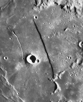
First, the cratering event creates a shock wave that doesn’t ‘stop’ in the impact’s general area, but continues to travel out across the moon. If this wave contains sufficient energy, it will cause faulting in the bedrock (the Straight Wall is an example of this; Fig 18). It can also activate faults that already exist. Finally, it can loosen semi-stable materials on crater rims, producing landslides (Fig 19).
Upon impact, basins spread a thick ejecta blanket over a huge section of the moon. These blankets accumulated into a layer several kilometers thick, called the megaregolith. On top of it is a layer of fine, dusty material called the regolith. This was produced by smaller meteorites/micrometeorites pulverizing the upper layers of the megaregolith. The regolith can be over 15 meters thick on the lunar highlands, and up to 8 meters thick on the mare. Because the regolith is so thick, it acts as a protective shield to the underlying structures (megaregolith, lava flows). Micrometeorites and small meteorites are not able to pierce it. Only meteors around 3 meters in diameter can now reach the megaregolith (depending on their velocity).
Unusual Craters on the Moon
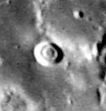
Many unusual cratering forms appear on the moon. Here we will examine only a few. First, there are concentric ring craters (Fig 20: Hesiodus A). This type of crater occurs when the lunar surface has two layers, with the upper layer being relatively unconsolidated, and the bottom layer being relatively consolidated. Here the shock wave easily excavates the upper layer, but has trouble excavating the bottom layer. Indeed, it only excavate the central region of the bottom layer, for this is where the energy is the greatest. To the outside of this, it reflects off the bottom layer, leaving a flat, ring-like floor. Thus, the form of the crater, from outside to inside is as follows: the crater rim; a steep walled region leading down to a floor; a circular, flat middle region; and a bowl shaped central depression.
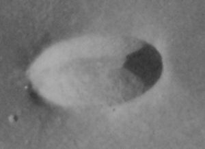
Another unusual crater type is the elongated form (Messier, fig. 21). Elongated craters have a variety of mechanisms for formation, but the most common is that of an oblique impact. When bolides (impacting object) have an angle of greater than 30 degrees, the crater will be circular and the ejecta will be symmetrical. When the angle is between 10 degrees and 30 degrees, the crater will be circular, but the ejecta will be assymetrical (fig. 22). When the angle is less than 10 degrees, then the crater also becomes elongaged, as in figure 21.
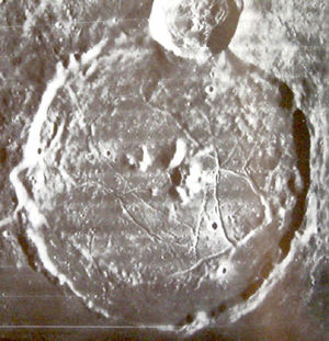
A final unusual crater type is the floor-fractured crater (fig 23). These craters have a series of rilles along the floor. Such craters generally occur along the margins of basins or large lava ponds, and their mechanism of formation is related to these magma features. When a crater is formed, the shock wave creates faults and fractures in the bedrock underneath it. If magma is rising in the general region of such faults, it will preferentially track up these zones of weakness. The magma then accumulates underneath the floor of the crater. If sufficient pressure is exerted on the floor, it will up-bow until failure occurs, creating the fractures seen in figure 23.
Articles in this Series
- Geologic Processes on the Moon - Parent Article
- Cratering on the Moon - First Article (You Are Here)
- Tectonic Processes - Second Article
- Volcanism - Third Article

